Other series
SD-26 typeG/E/C
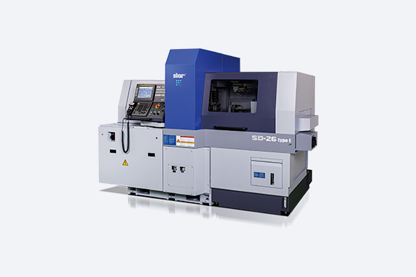
The long-awaited new machine, born from our focus on the needs for the 26-dia. Class.
- Max.machining diameter

- Tool Post

- Max.headstock stroke


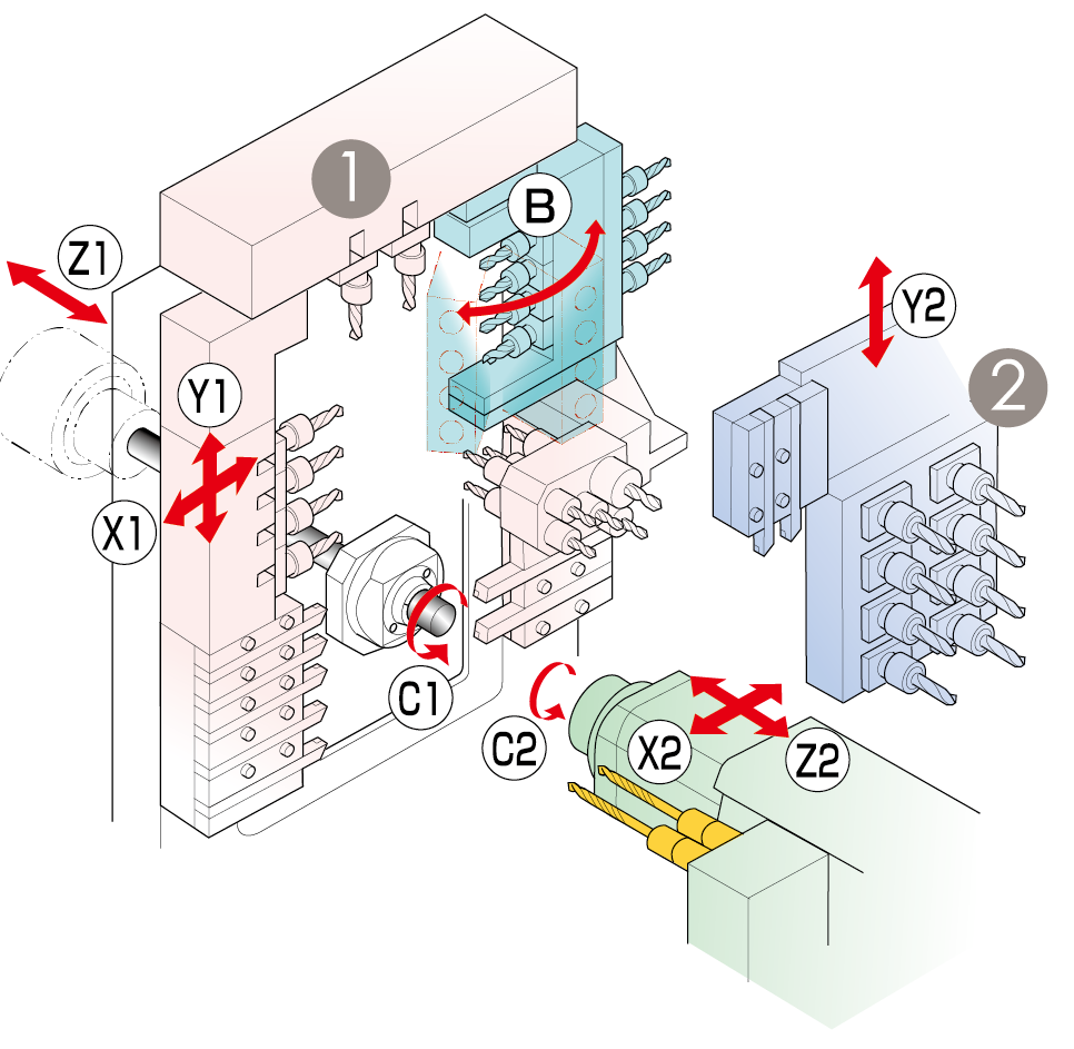
| Tool Post | Tooling | ||
|---|---|---|---|
| ① |
 |
Turning tool | 7 tools |
| Frong-end working tool | 7 tools | ||
| Rear-end working tool | 5 tools | ||
| Power-driven tool | 4 tools or 4 Pos. | ||
| Cartridge type with B axis control | 2 Pos. | ||
| Power-driven tool with B axis control | 1 pos. (Front 4 tools + Rear 4 tools) | ||
| ② |
 |
Rear-end working tool | 8 tools |
| Stationar tool | max.8本 | ||
| Power-driven tool | max.8本 | ||
| Item | SD-26 type G/E/C | ||
|---|---|---|---|
| Max.machining diameter | ø 26mm (1-1/64in) | ||
| Max.headstock stroke | Standard | 260mm (10-15/64in) | |
| R.M.G.B.unit | 223.5mm (8-51/64in) | ||
| N.G.B.type | max.65mm (2-35/64in) | ||
| Number of turning tools | 5 tools on the front + 2 tools on the rear | ||
| 5-spindle sleeve holder |
Number of tools | Front : 5 tools | |
| Rear : 5 tools | |||
| Max.drilling capability | ø 13mm (33/64in) | ||
| Max.tapping capability | M12 x P1.75 | ||
| 2-spindle sleeve holder |
Number of tools | 2本 | |
| Max.drilling capability | ø 10mm (25/64in) | ||
| Max.depth of hole | 100mm (3-15/16in) | ||
| Power-driven att. | Number of tools | Power-driven tool with B-axis : At 1 position(Front 4 tools + Rear 4 tools) | |
| Number of tools | Front | Cross milling : 4 tools or Cartridge type : At 4 position | |
| Upper | Cartridge type : At 2 position | ||
| Max.drilling capability | Tilting head unit | ø 8mm (5/16in) | |
| Front/Upper | ø 10mm (25/64in) | ||
| Max.tapping capability | Tilting head unit | M8 x P1.25 | |
| Front/Upper | M8 x P1.25 | ||
| Spindle speed | max.8,000min-1 | ||
| Drive motor | 2.2kw(Continuous) / 3.0kw(5min./30%ED) | ||
| Rapid feed rate | 36m/min(X1,Y1,Z1,X2,Z2) | ||
| Main spindle indexing angle | C-axis control | ||
| Main spindle speed | max.10,000min-1 | ||
| Main spindle motor | 5.5kw(Continuous) / 7.5kw(10min./25%ED) | ||
| Dimensions (WxDxH) | 2,550 x 1,300 x 1,995mm | ||
| Weight | 3,600kg | ||
| Power consumption | 9.9KVA | ||
| Item | SD-26 type G/E/C | ||
|---|---|---|---|
| Max.chucking diameter | ø 26mm (1-1/64in) | ||
| Max.length for front ejection | 90mm (3-17/32in) | ||
| Max.work projection length | 40mm (1-9/1/6in) | ||
| 8spindle backworking unit |
Number of tools | 8 tools | |
| Max.drilling capability | Stationary tool | ø 13mm (33/64in) | |
| Power-driven att. | ø 8mm (5/16in) | ||
| Max.tapping capability | Stationary tool | M12 x P1.75 | |
| Power-driven att. | M6x P1.0 | ||
| Sub spindle indexing angle | C-axis control | ||
| Sub spindle speed | max.10,000min-1 | ||
| Sub spindle motor | 3.7kw(Continuous) / 5.5kw(10min./40%ED) | ||
Standard Accessories and Functions
- CNC unit
FANUC 31i-B5 Plus (type G)
FANUC 32i-B Plus (type E)
FANUC 0i-TF Plus (type C) - 10.4-inch color LCD display
- Pneumatic unit
- Coolant level detector
- Automatic centralized lubrication unit
- Door Interlock unit with Locking System
- Cs contour control (Main/Sub)
- Spindle clamp unit (Main/Sub)
- Cooling unit (Main spindle/ Drive unit for gang tool post)
- Revolving guide bush unit
- Drive unit for revolving guide bush
- Air purge unit for revolving guide bush
- Main/Sub collet sleeve
- Gang-type 5 station tool holder 16 mm Gang-type 5 station tool holder 16 mm
- 4 Spindle cross drilling unit ER16
- 4 Spindle opposing unit with B axis control function (type G/E) Angle adjustable 4 spindle opposing unit (type C)
- 5 spindle sleeve holder
- 2 spindle sleeve holder
- Broken cut-off tool detector
- Back attachment
- 8 spindle back working unit with Y axis control function
- Drive unit for 8 spindle back working unit
- Parts separator
- Parts conveyor
- Sub spindle air purge unit
- Coolant pump 400W ver. (Main/Sub)
- Work light
- Earth leakage breaker
Optional Accessories and Functions
- Gang-type tool holder Coolant thru (5 station/2 station)
- 4 Spindle cross drilling unit cartridge
- Non-Guide Bush Version
- Revolving magic guide bush unit
- Coolant flow detector
- Coolant flow detector interface
- Coolant pump with de-aeration function
- Coolant chiller
- Water separator
- Beacon
- Beacon interface
- Parts ejector with Spring
- Parts ejection detector
- Parts ejector with air cylinder
- Parts separator unit long parts ver.
- Parts ejector with guide tube
- Parts stopper unit
- Coolant unit (6.9MPa/2.5MPa/0.7MPa)
- Coolant unit signal cable 46 contacts Ver.
- Coolant unit power cable
- Coolant valve
- Coolant piping
- Expanded I/O module unit
- Terminal base
- Reducing valve
- Main spindle inner tube
- Steady rest for feed rod
- Automatic bar feeder interface
- Steady rest unit cover
- Safety cover
- LAN/RS232C interface
- Transformer
- Transformer CE marking version 20kVA
- CE/UKCA marking version
MACHINE SERIES
- SB series
- SB-12RG
- SB-16III
- SB-20R typeG
- SB-20RII
- SR series
- SR-10J typeC
- SR-20JII
- SR-32JIII
- SR-38 typeB
- Other series
- SL-7/10
- SW-12RII
- SP-20
- SW-20
- SV-20R
- ST-20
- SD-26 typeS
- SD-26 typeG/E/C
- SX-38
- ST-38