Other series
SW-20
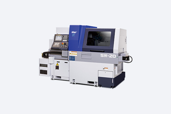
Mechanicl and control design to minimize machining time and maximize efficiency.
- Max.machining diameter

- Tool Post

- Max.headstock stroke

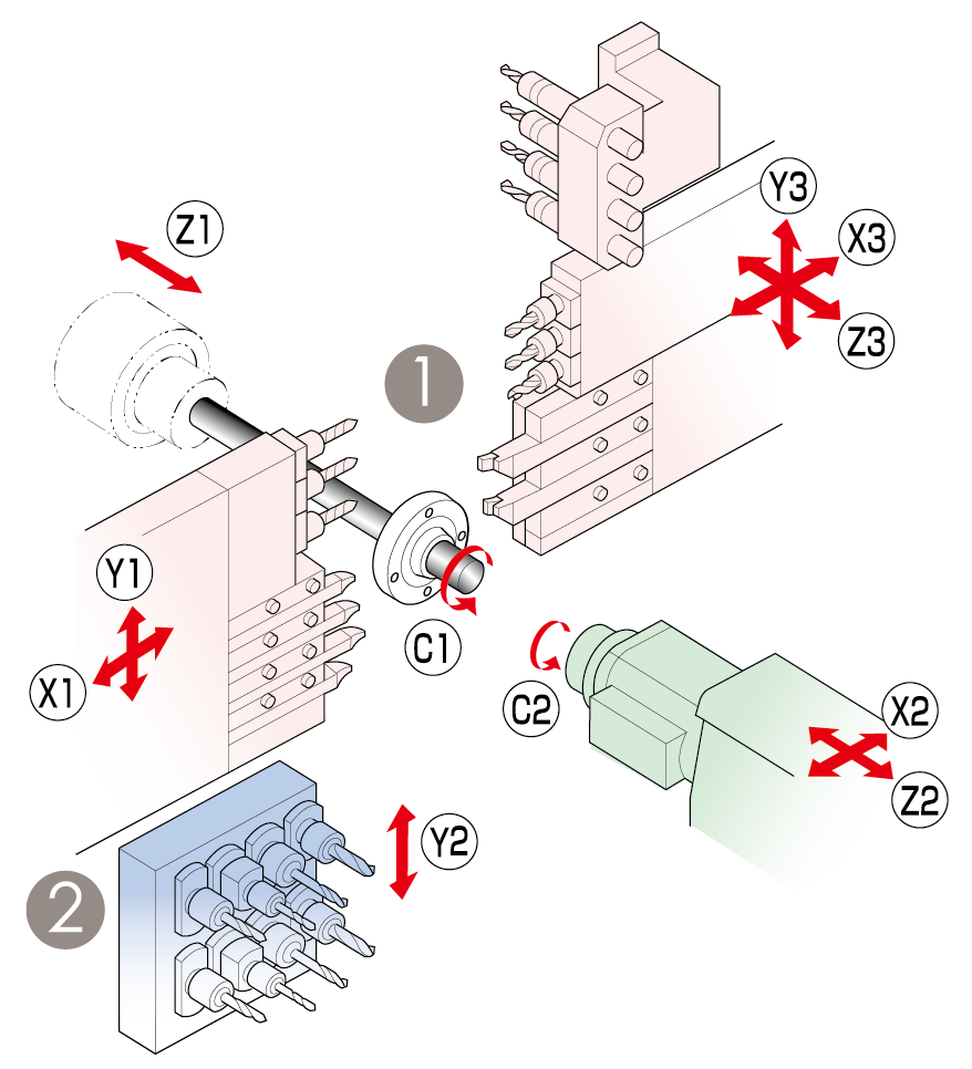
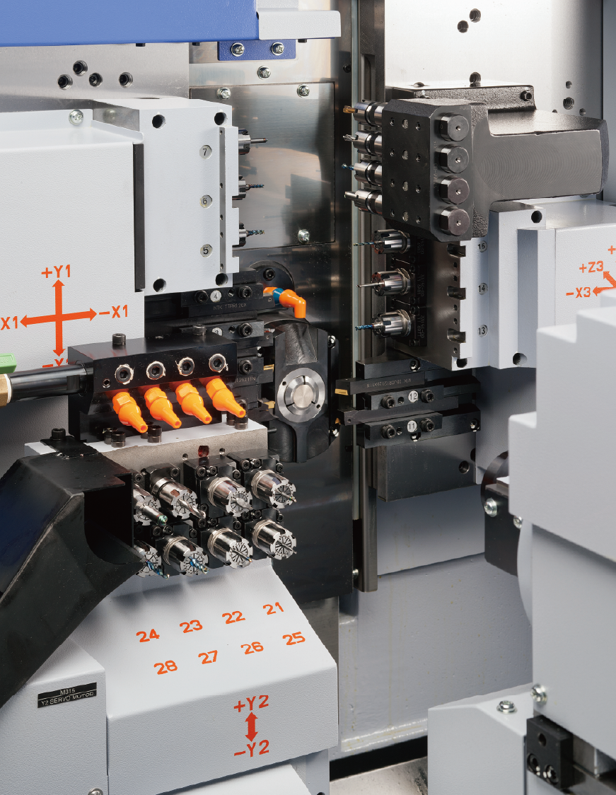
| Tool Post | Tooling | ||
|---|---|---|---|
| ① |
 |
Turning tool | 6 tools |
| Front-end working tool | 4 tools | ||
| Rear-end working tool | 4 tools | ||
| Power-driven tool | 6 tools | ||
| ② |
 |
Back 8-spindle unit | 8 tools |
| Stationary tool | max.8 tools | ||
| powered tool | max.6 tools | ||
| Item | SW-20 | ||
|---|---|---|---|
| Max.machining diameter | ø20mm(25/32in) | ||
| Max.headstock stroke | 205mm(8in) | ||
| Tool post configuration | Front | Turning tool + Power-driven tool | |
| Rear | Turning tool + 4-spindle sleeve holder+ Power-driven tool | ||
| Turning tools | Front | 4 tools (□12mm / □16mm) | |
| Rear | 2 tools (□12mm / □16mm) | ||
| 4-spindle sleeve holder |
Number of tools | Front : 4 tools | |
| Rear : 4 tools | |||
| Max.drilling capability | ø10mm(25/64in) | ||
| Max.tapping capability | M8×P1.25 | ||
| Power-driven att. | Number of tools | Front | 3 tools |
| Rear | 3 tools | ||
| Max.drilling capability | ø8mm(5/16in) | ||
| Max.tapping capability | M6×P1.0 | ||
| Spindle speed | max.8,000min-1 | ||
| Drive motor | 1.0kw(Continuous) / 1.2kw(5min./30%ED) | ||
| Rapid feed rate | 35m/min(Y1,Z1,X2,Z2,Y3) , 20m/min(X1,Y2,X3,Z3) | ||
| Main spindle indexing angle | C-axis control | ||
| Main spindle speed | max.10,000min-1 | ||
| Main spindle motor | 2.2kw(Continuous) / 3.7kw(10min./25%ED) | ||
| Dimensions (W×D×H) | 2,588×1,300×1,765mm | ||
| Weight | 3,400kg | ||
| Power consumption | 4.8KVA | ||
| Item | SW-20 | ||
|---|---|---|---|
| Max.chucking diameter | ø20mm(25/32in) | ||
| Max.length for front ejection | 80mm(3-5/32in) | ||
| Max.work projection length | 30mm(1-3/16in) | ||
| 8-spindle unit | Number of tools | 8 tools | |
| Max.drilling capability | Stationary tool | ø10mm(25/64in) | |
| Power-driven att. | ø8mm(5/16in) | ||
| Max.tapping capabilily | Stationary tool | M8×P1.25 | |
| Power-driven att. | M6 ×P1.0 | ||
| Sub spindle indexing angle | C-axis control | ||
| Sub spindle speed | max.10,000min-1 | ||
| Sub spindle motor | 2.2kw(Continuous) / 3.7kw(10min./25%ED) |
||
Standard Accessories and Functions
- CNC unit FANUC 31i-B5
- Operation panel 10.4-inch color LCD display
- Pneumatic unit
- Automatic centralized lubrication unit
- Coolant level detector (lower limit)
- Door interlock system
- Broken cutoff tool detector
- Drive unit for revolving guide bush
- C-axis control unit (Main/Sub)
- Spindle clamp unit (Main/Sub)
- Drive system for power-driven tool (for the tool posts 1 and 2)
- 4-Spindle sleeve holder
- Back 8-Spindle unit
- Drive unit for power-driven attachment B
- Parts ejector (Spring type)
- Air purge for revolving guide bush
- Sub spindle air purge unit
- Sub spindle air blow unit
- Parts separator
- Automatic bar feeder interface
- Work light
- Leakage breaker
Optional Accessories and Functions
- Revolving guide bush
- Rotary magic guide bush unit
- Collet (Main/Sub)
- 2-station tool holder (12mm/ 16mm)
- 4-station tool holder 12mm/16mm)
- Parts conveyor
- Parts ejector
- Parts ejector (Spring type rotary ver.)
- Parts separator unit A
- Barstock gripping unit
- Parts ejector with guide tube
- Parts stopper unit
- Main spindle inner tube
- Coolant unit 2.5MPa
- Coolant unit 6.9MPa
- Coolant unit 0.7MPa
- Coolant pipings
- Coolant flow detector
- Parts ejection detector
- Warning light
- Water separator
- Compliant with the RS-232C interface
- Transformer
- Transformer CE marking version
- Transformer CE marking specifications
MACHINE SERIES
- SB series
- SB-12RG
- SB-16III
- SB-20R typeG
- SB-20RII
- SR series
- SR-10J typeC
- SR-20JII
- SR-32JIII
- SR-38 typeB
- Other series
- SL-7/10
- SW-12RII
- SP-20
- SW-20
- SV-20R
- ST-20
- SD-26 typeS
- SD-26 typeG/E/C
- SX-38
- ST-38